First, a short recap of what this project is doing: the Wi-Fi stack for the ESP32 (a popular, cheap microcontroller) is provided through a binary blob. We’re trying to reverse engineer the software and hardware to build our own open-source Wi-Fi stack. If this sounds interesting, I recommend you read the first and second blog posts. However, this is not necessary to read the rest of this blog post.
One problem we encountered while reverse engineering the Wi-Fi hardware, is that there are a lot of Wi-Fi packets flying through the air: even when idle, most access points broadcast a beacon packet about ten times per second. Combined with the data packets that are also sent between access points and clients in the neighbourhood, this adds up to a lot of packets per second. One tool we use in reverse engineering, is a Wi-Fi dongle in monitor mode: in that mode, the dongle captures all packets it sees, even packets not addressed to the dongle’s MAC address. This deluge of packets sometimes makes it hard to find the single packet the ESP32 did or did not send; in most scenarios, you could filter on MAC address, but since we’re still reverse engineering the hardware, we sometimes don’t know the MAC address a packet will be sent with.
Failed attempts Link to heading
A simple (albeit not very practical) way to fix this, is to go out into the woods where there are no Wi-Fi devices. A better approach is to ‘insulate’ the ESP32 and Wi-Fi dongle from outside Wi-Fi transmitters. My first try at this was to directly connect the antenna connector of the ESP32 with the antenna connector of the dongle (with an attenuator in between, to make the signal weaker not to overpower the receiver).
However, this did not work: outside packets still leaked in. My second try involved a very basic Faraday cage: a paint tin with a cut-out for the USB leads of the dongle and ESP32. To try to reduce RF leaking in via the USB leads, I added several ferrite chokes and closed the hole with copper tape. This unfortunately did not work as well as people online told it would; it only further attenuated outside packets with 10 dB. A 10× decrease in power might sound impressive, but it’s really not: my laptop can receive packets as quiet as -90 dBm; right next to an access point the packets are about -35 dBm, so attenuating with only 10 dB is not enough by a long shot.
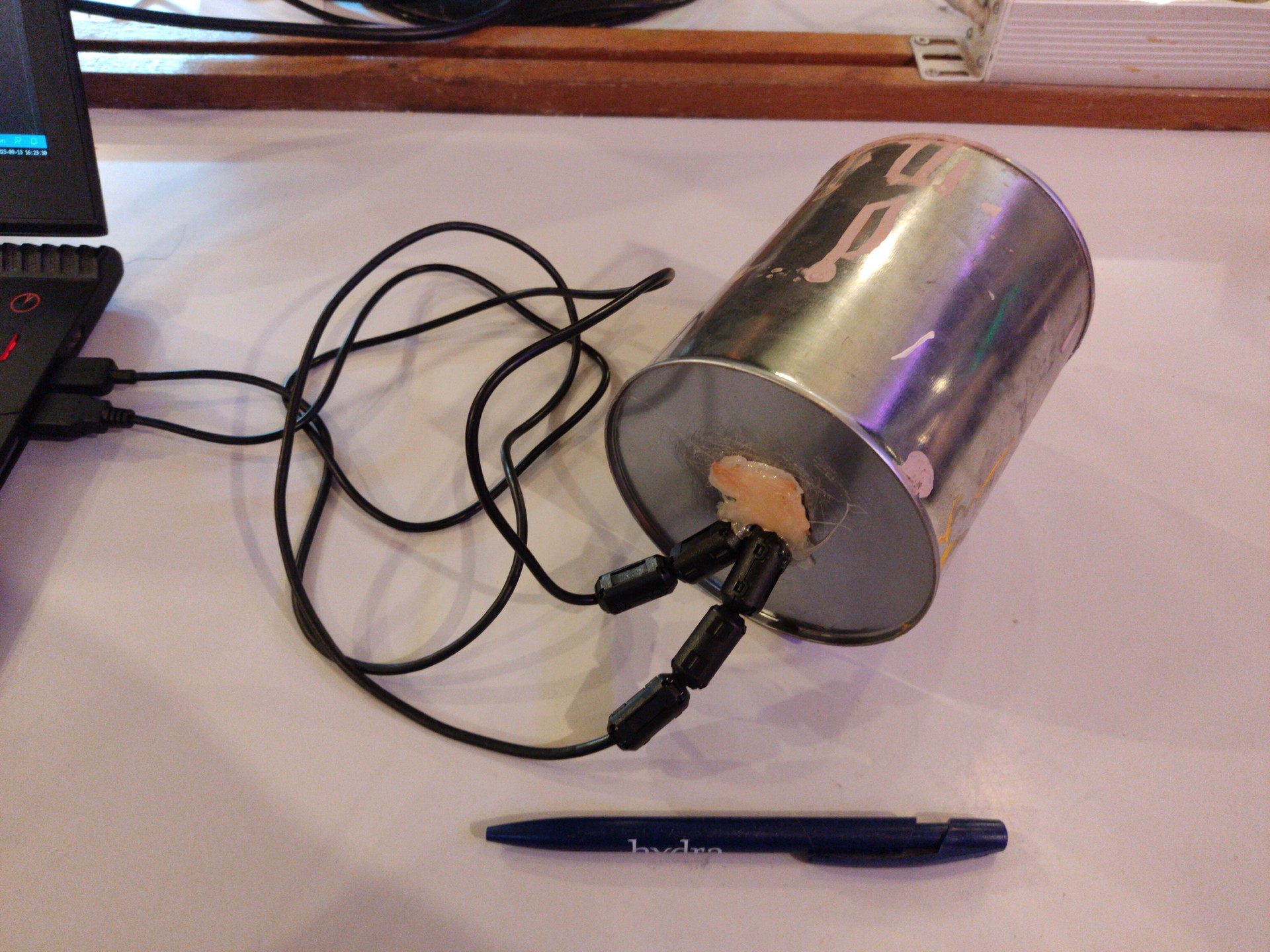
I also tried putting my phone in a (turned off!) microwave, but this did not work either, it was still connected to the Wi-Fi access point.
Proper Faraday cage Link to heading
While researching on how to build a proper Faraday cage that is also affordable, I came across the paper ‘Building and Testing an Economic Faraday Cage for Wireless, IoT Computing Education and Research’ that seemed pretty good: for 793 USD, they built a Faraday cage with data and power passthrough: they accomplished the data passthrough by using an Ethernet-to-fiber converter; they accomplished the power passthrough by using a second-hand power line filter from a MRI chamber. Simply explained, the paper proposes having two cabinets: an inner cabinet, covered in conductive fabric except where the door is, and an outer one, where the door is covered in fabric, sealing against the inner cabinet when the door is closed. If this is not entirely clear, don’t worry, I’ll have pictures later.
There are, in my opinion, some flaws in that paper:
- they mention the bill of materials, but don’t give important specifications about what exactly it is they used. For example, their bill of materials states ‘Used 20A Powerline Filter’, but this is the most specific description of the power line filter in the paper. By emailing the original authors, I got to know that they used a Lindgren EMI/RFI filter, ELUL-2020, obtained on eBay.
- which brings me to the second point: they use second-hand material for both the power line filter (120 USD in the paper) and the cabinet (5 USD in the paper). Now, I don’t have anything against re-using components; I sometimes go to the scrapyard to scavenge useful electronic components (motors, displays, …), but you cannot rely on the availability of those components. While it is true that in the US, similar filters can be bought for ~200 USD on eBay, you cannot rely on those filters staying available in the second-hand market. Furthermore, in Belgium, the country where I live, there don’t appear to be any EMI power filters available on the online second hand markets. The import costs and shipping charges for buying a used power line filter from the US would be prohibitive.
- using second-hand materials in something where the goal is to make it low-cost feels a bit like cheating: the materials are low-cost because you did a good job in obtaining something expensive for a low price, not because the materials are inherently low-cost. A new EMI power line filter is so expensive that places selling them don’t even display the price (“if you have to ask the price, you can’t afford it”).
I will try to only use materials that are commonly available, and link to what exactly I bought. The main differences between the approach in the paper and my approach are:
- I built the inner and outer cabinets myself, from wood. No special tools are needed, only a drill.
- Instead of trying to pass through power, I’ll put a lead-acid battery inside the Faraday cage and use buck-boost converters to convert to the necessary voltages for the fiber-optics converter and devices under test. This will lower the costs dramatically, to the point where even when we’re using all-new components, the price will still be lower than the price described in the paper.
Pictures! Link to heading
(Please excuse me for the bad image quality)
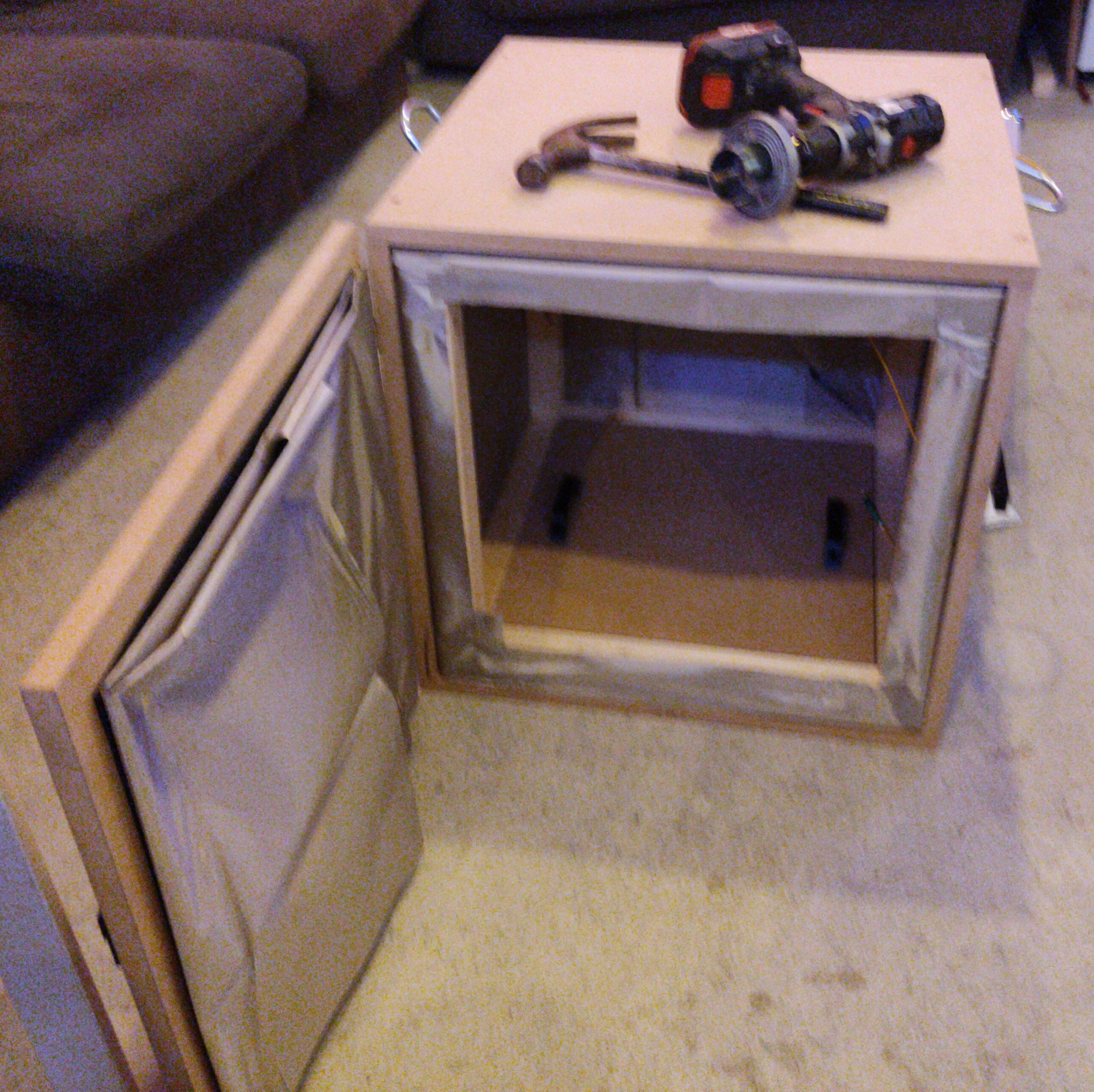
First of all, a picture of the completed Faraday cage where I’d like to call attention to:
- this consists of two parts that slide into each other: the outer cabinet, made from medium-density fiber board (MDF board), and the inner cabinet, made from a wooden skeleton covered with conductive fabric on five sides.
- there is conductive fabric on the inner side of the door. There is foam tape between the fabric and the wood on the front side of the inner cube; when you close the door, the foam tape is compressed, pressing the fabric of the inner cube tightly against the fabric of the front door, creating an RF tight seal.
- there is a black latch on the door that can keep the door shut (not shown very well here, but I’ll show a better picture later).
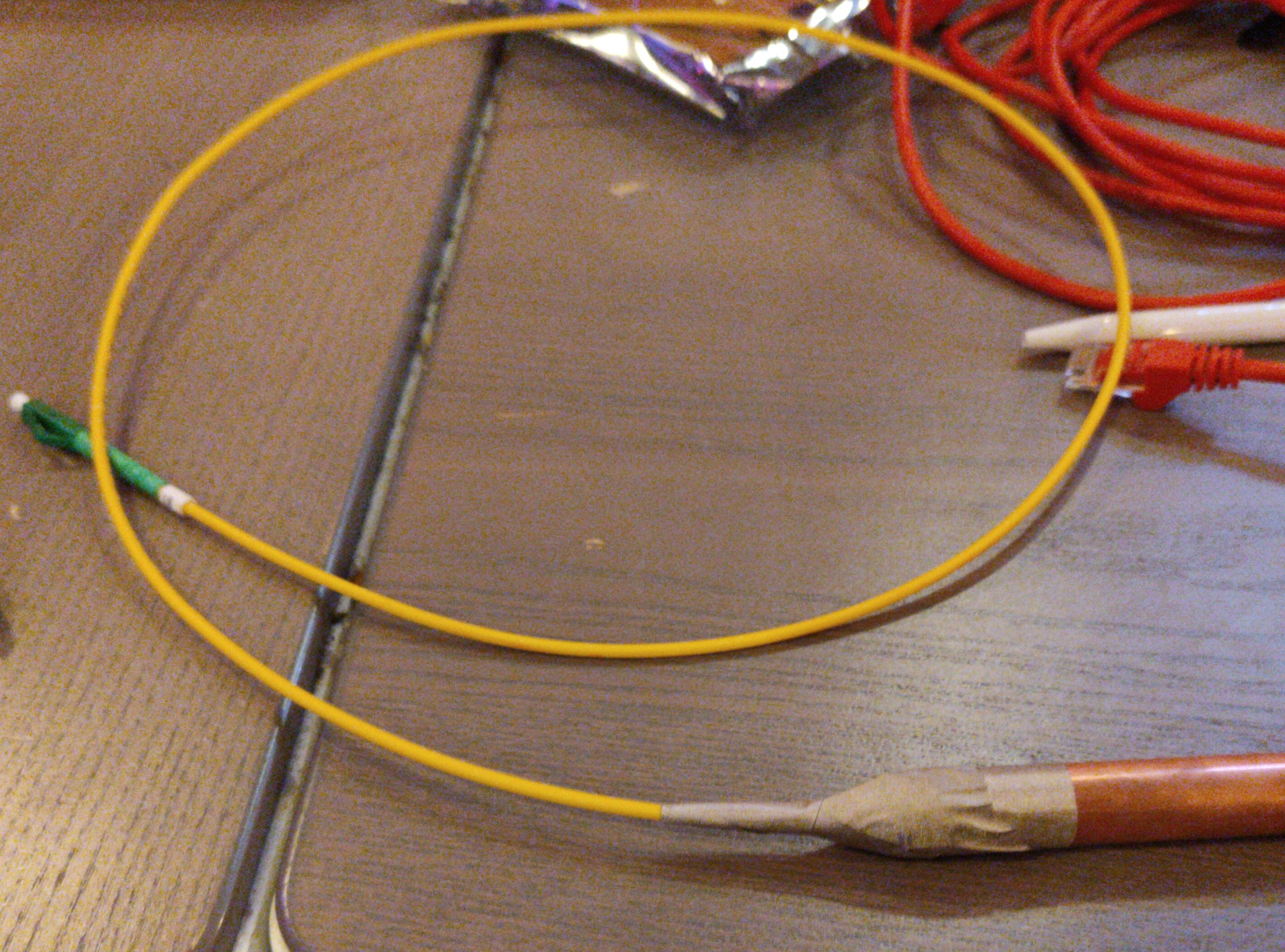
- in the top right corner, you can see a yellow fiber entering the cage from behind.
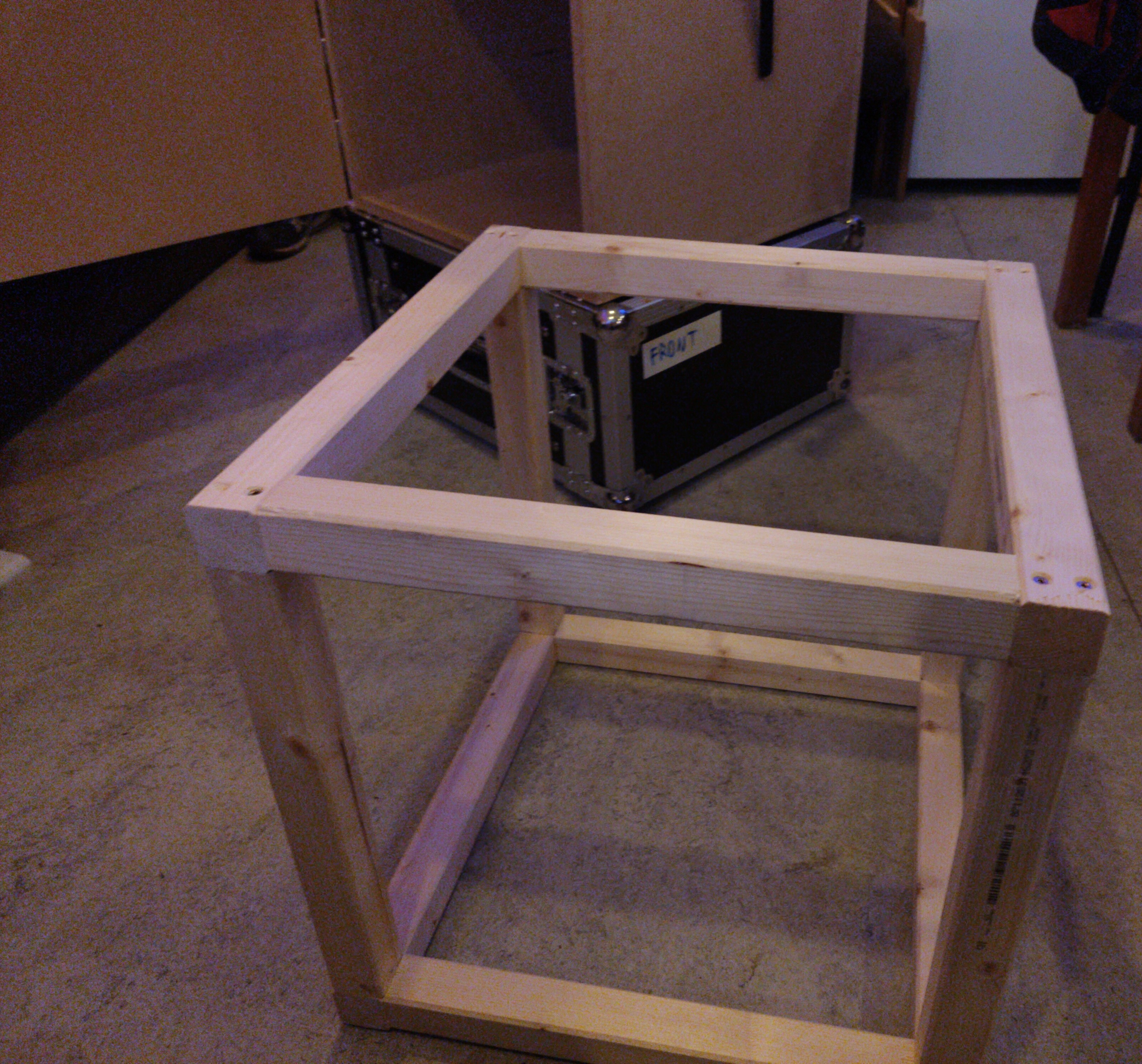
This is the inner cube, constructed from wood, before it was covered with conductive fabric on five sides.
Here, you can see the two fiber-to-Ethernet converters. I used bidirectional converters: this means that only one fiber is used for both transmitting and receiving data; as opposed to unidirectional fiber that has a TX/RX pair. This was done to minimize the size of the connector, which in turn would make it possible to fit through a smaller diameter copper tube.
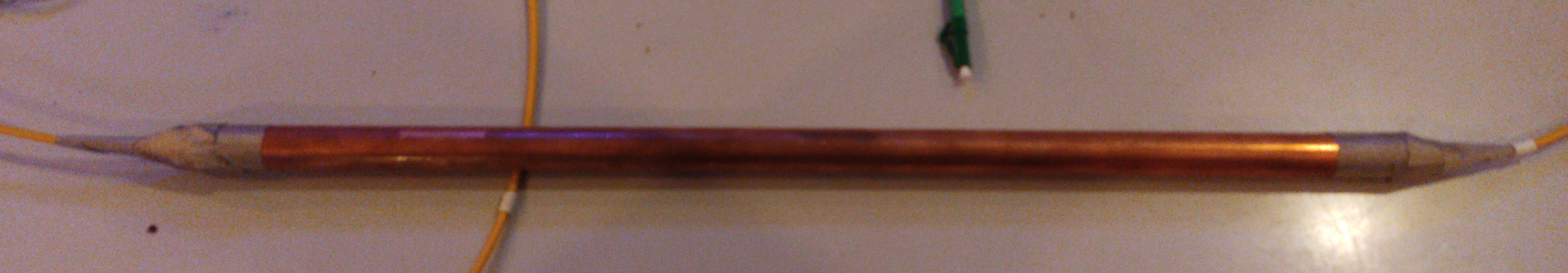
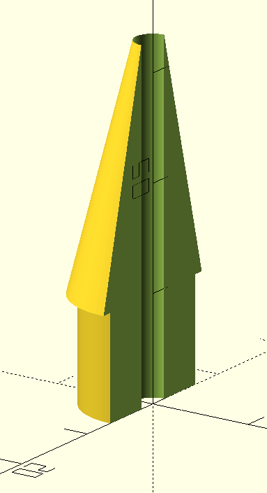
This is a copper pipe that has the fiber going through it. On both sides of the pipe, a small 3D printed cone was added to gently convert the diameter of the outer pipe to the diameter of the fiber. Conductive tape was used to seal the hole in the copper pipe: only a very small hole where the fiber exits, remains. Since this hole is sufficiently small compared to the wavelength of the 2.4 GHz radio waves, the radio waves cannot enter via there.
This copper tube was then inserted through a hole in the fabric on the back of the inner cube. It was again taped with conductive tape to both the inside and outside to form a good seal.
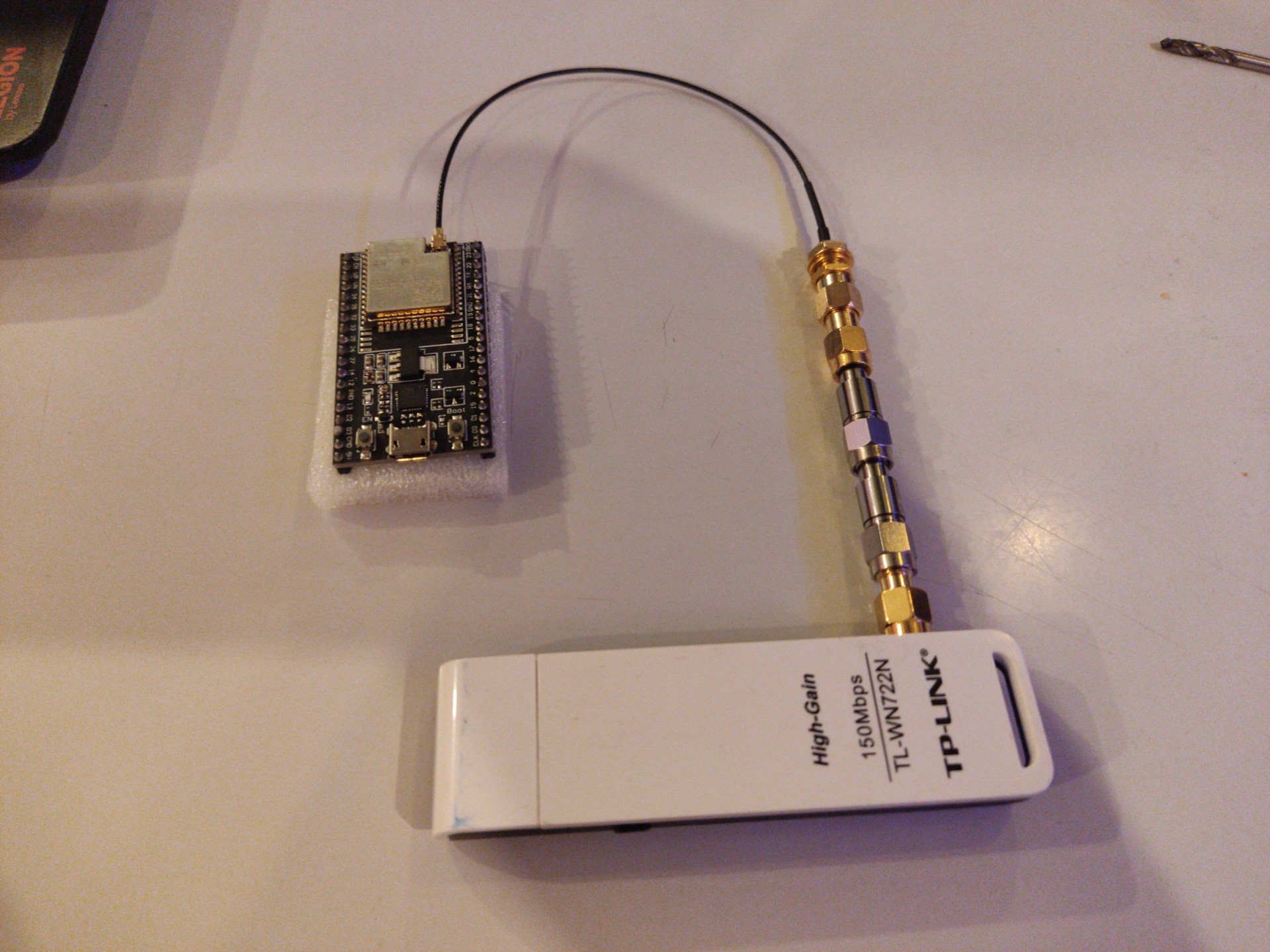
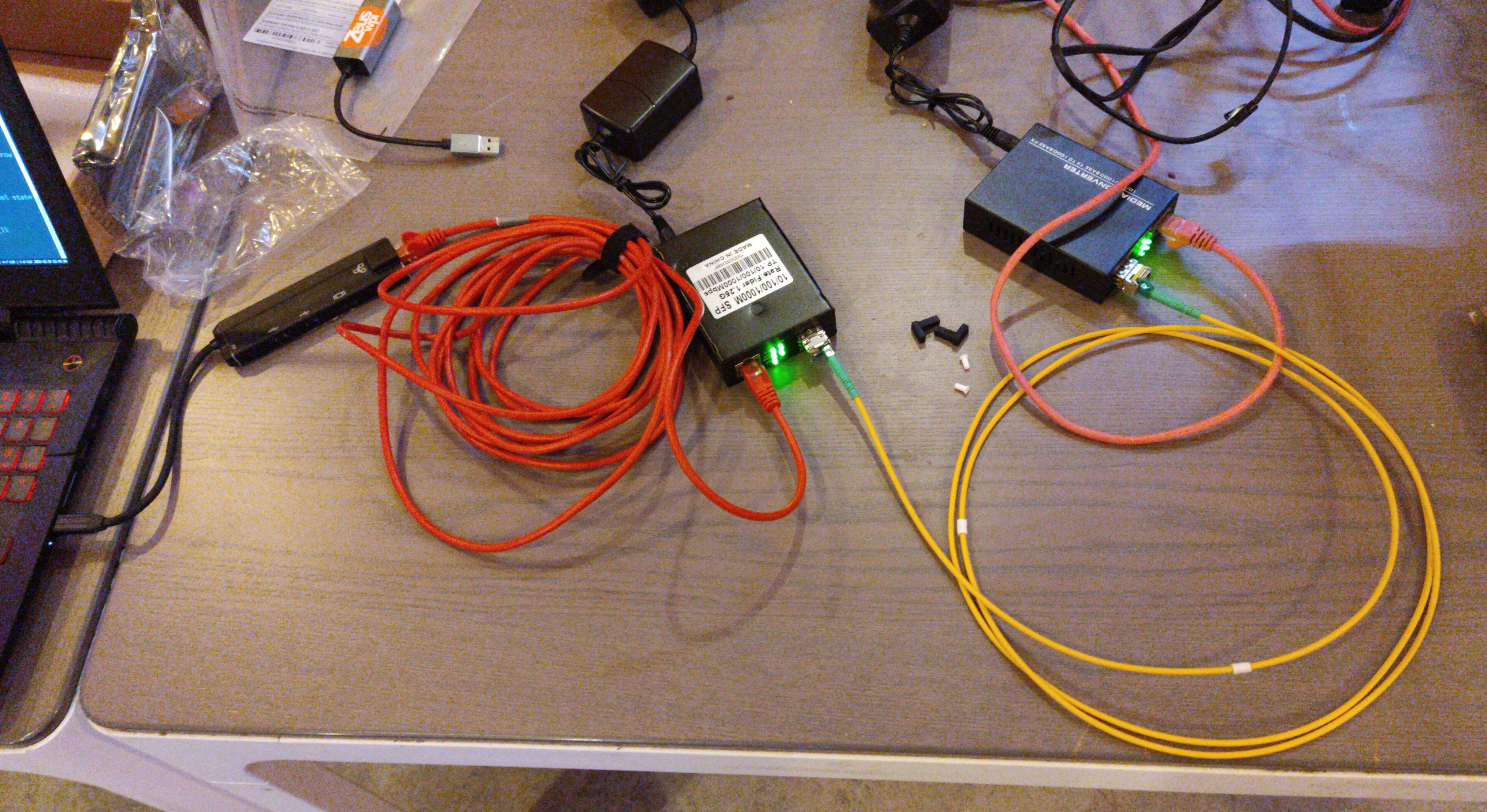
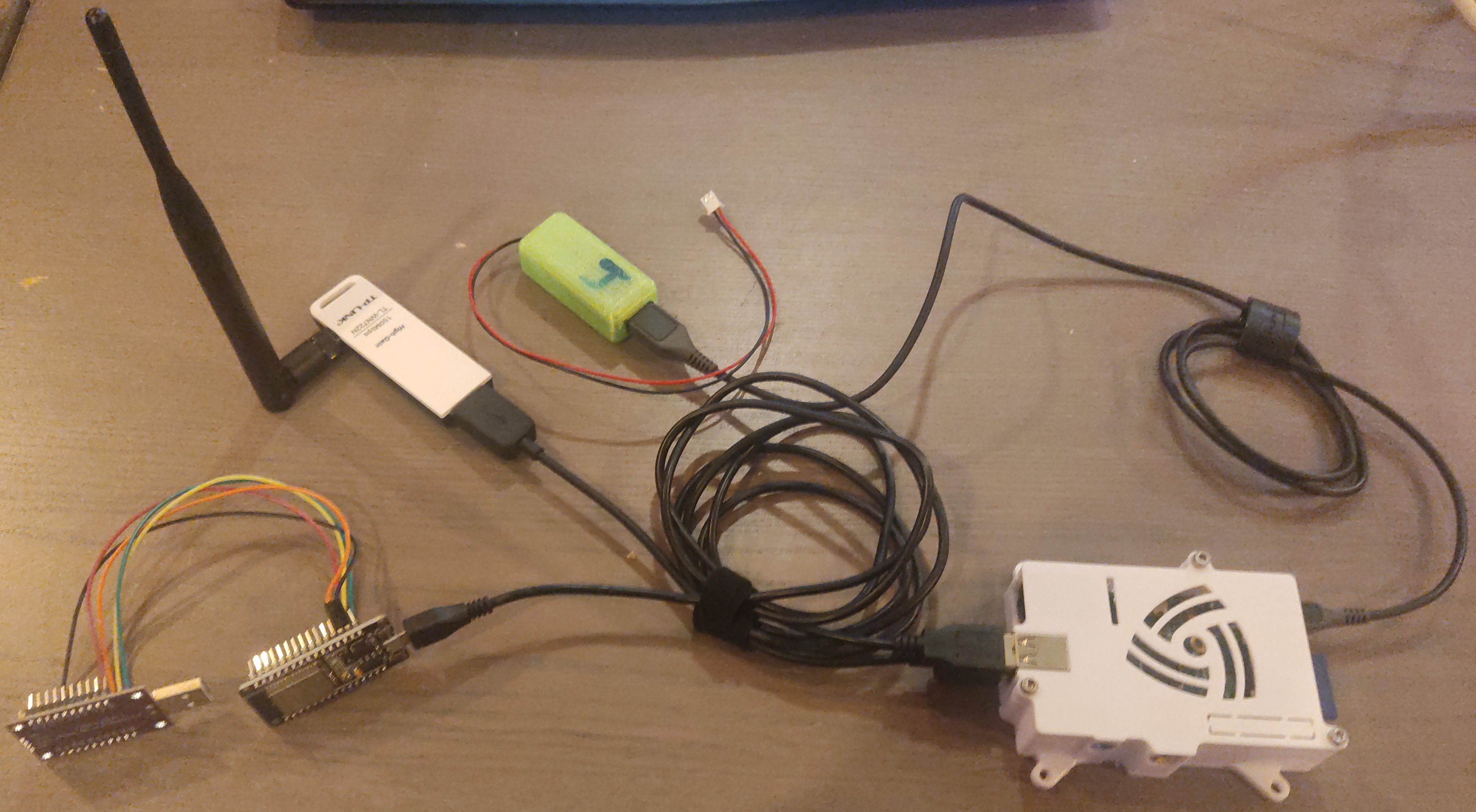
This is the test setup that is placed inside the Faraday cage. It consists of:
- A Raspberry Pi. This runs usbip, so that the USB devices connected to the Pi can be used from other computers on the network.
- A 5V USB buck converter (green case) converting the 12V from the battery to 5V for the Pi
- A TP-Link TL-WN722N v1 Wi-Fi dongle, used to capture packets (it can be put in monitor mode)
- An ESP32, connected to a JTAG debugger (not connected via USB at the moment)
Testing Link to heading
The Faraday cage was then tested by sniffing packets using the Wi-Fi dongle inside. I first captured packets for 10 minutes while the door was open (so RF could enter), then captured packets for 10 minutes after the door was closed.
When the door was closed, no packets were captured at all. So, as to still give an approximate lower bound by how much the Faraday cage attenuates signals at 2.4 GHz, I used both the strongest and weakest signal strength when the door was open:
>>> from scapy.all import *
>>> scapy_cap = rdpcap('faraday_captured_packets_door_open.pcapng')
>>> max(p.dBm_AntSignal for p in scapy_cap)
-12
>>> min(p.dBm_AntSignal for p in scapy_cap)
-81
>>> (-12) - (-81)
69
The weakest signal my wireless dongle could still receive was -81 dBm. The strongest signal that arrived was -12 dBm. Since the Faraday cage blocked all packets, the power of even the strongest signal would have to have been attenuated to below -81 dBm for it to not be able to be received anymore. So, a lower bound of 69 dB attenuation is established. I know that this might not be entirely correct (the wireless dongle might not be calibrated, the geometry of the Faraday cage could have increased signal strength when the door was open, etc.), but I think it gives a good enough indication.
The Wi-Fi dongle I have, does not do 5GHz Wi-Fi. To still test that frequency, I placed my phone in the Faraday cage while it was connected to a 5GHz Wi-Fi access point, and was not able to ping it anymore after I closed the door; I was also unable to call it.
Bill of materials Link to heading
| Item | Price in EUR (1 EUR = 1.1 USD) | Link, if necessary |
|---|---|---|
| MDF board 244×122 cm | 29.99 | |
| 3× wooden beam 44×44mm, 210cm | 9.27 | |
| copper pipe, 15mm outer diameter, 1m (although you only need about 0.5m) | 10.99 | |
| hinges (could likely also be 3D printed) | 7.78 | |
| (optional) handles for outer cube | 10.69 | |
| wood screws; I used 4mm × 40mm for outer MDF cube; 4mm × 60mm screws for inner cube. I didn’t have any wood screws before this project, so I bought in bulk for future projects. The 10 EUR here is an upper bound estimate | 10 | |
| foam tape: I used 20 mm width × 3 mm height × 10 m length tape | 7.45 | https://web.archive.org/web/20240113175203/https://www.amazon.com.be/dp/B09KBH7WT1 |
| conductive fabric, 3× 110 cm by 91 cm. I used TitanRF fabric, this was the only fabric that came with a test report | 84 | https://web.archive.org/web/20240113174610/https://www.amazon.com.be/-/nl/Darkness-Military-geleidende-RF-signalen-Bluetooth/dp/B01M294MGK/ |
| conductive tape; 2.54 cm × 3.05 m | 12 | https://web.archive.org/web/20240113174817/https://www.amazon.com.be/-/nl/TitanRF-Faraday-Tape-High-Shielding-RF-sluitingen/dp/B07CRLCGCH/ |
| 1 pair gigabit Ethernet to BiDi fiber converter | 65.23 | https://web.archive.org/web/20240113172956/https://www.amazon.com.be/-/nl/multimedia-singlemode-LC-transceiver-inbegrepen/dp/B09MD4BBFD/ |
| single OS2 LC/LC fiber optic cable, 2m | 7.99 | https://web.archive.org/web/20240113174655/https://www.amazon.com.be/-/nl/nexinex-Glasvezel-patchkabel-Simplex-single-mode/dp/B0CDQ6YXPS/ |
| buck converters (13.99 for 12; I only used two here) | 2.33 | |
| 3d printing filament (way less than 200g, but let’s take that) | 4 | |
| Ultracell UL18-12 12V 18Ah lead-acid battery | 29.66 |
For a grand total of 291.38 EUR, or about 318 USD.
You’ll need to 3D print various items, those are detailed at https://github.com/esp32-open-mac/faraday_cage
Building tips Link to heading
Outer shell Link to heading
- Assemble outer shell. This is made from MDF, so be careful and definitely pre-drill before inserting screws, otherwise, you would split the MDF. Do this even for screws that advertise you don’t need to pre-drill.
- Attach hardware
- Hinges
- Latch to keep the door shut
- Optional: handles to lift the box
Framed cube Link to heading
- Assemble cube
- Attach all hardware
- Holders for copper tube
- Stand-offs for bottom plate
- Foam tape
- (Last!) Attach Faraday fabric, with thumbtacks. Don’t use a staple gun, you would tear the fabric.
If you have any questions, open a GitHub issue at https://github.com/esp32-open-mac/faraday_cage or send me an email via esp32-open-mac@devreker.be.