This is the fourth article in a series about reverse engineering the ESP32 Wi-Fi networking stack, with the goal of building our own open-source MAC layer. In the previous articles in this series, we reverse engineered hardware registers for transmitting and receiving Wi-Fi packets. We showed a demo that could transmit hard-coded UDP packets on an open Wi-Fi network. We also built a low-cost Faraday cage to be able to test our implementation without outside interference.
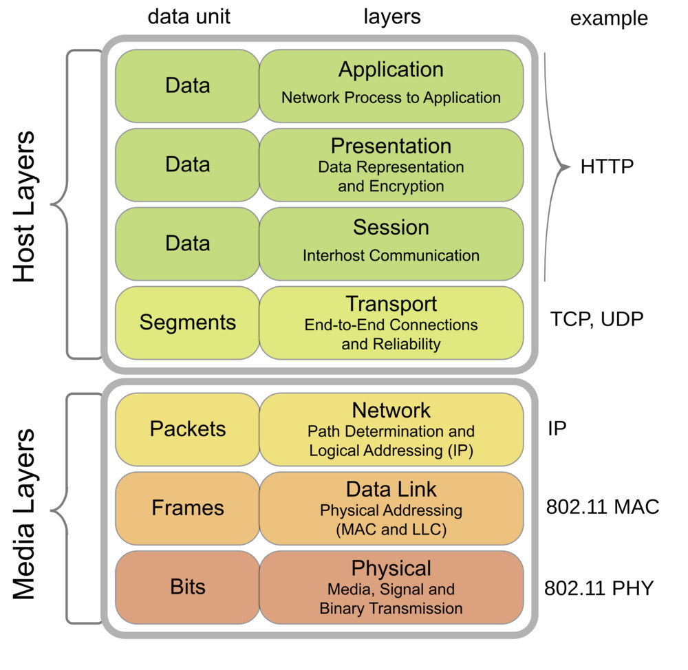
As a short recap, for this project, we implement a Wi-Fi driver for the ESP32 hardware. This means that we’re in the business of correctly setting and reading hardware registers, in order to send and receive packets. However, these packets need to be constructed by the higher layers in the OSI stack. We’d like to avoid having to implement the whole OSI stack, and would like to focus on only implementing the data link layer by reusing other software.

As part of the software in the ESP32 SDK (ESP-IDF), there is an open-source TCP/IP implementation: lwIP. This implements IP, DHCP, TCP, UDP, … To be able to use lwIP on the ESP32 with multiple types of nework adaptors, Espressif create ESP-NETIF, which acts as a kind of IO glue to tie a MAC stack into lwIP.
The API you need to implement to make a custom ESP-IDF IO driver is pretty simple:
esp_netif_receive(esp_netif_t *esp_netif, void *buffer, size_t len, void *eb)This function is called by the hardware driver to pass a buffer of received data to the upper network stack. The buffer consists of:
- 6 bytes destination MAC address
- 6 bytes source MAC address
- 2 bytes LLC data type
- data
The “ownership” of the buffer transfers to the upper network stack; once the upper level stack is done with it, it will call the
.driver_free_rx_bufferfunction to indicate that the buffer can be free’d/reused.
esp_netif_transmit(esp_netif_t *esp_netif, void *data, size_t len)This function is called by the upper layer MAC to transmit data. The buffer layout is the same as the one in
esp_netif_receive
Up to now, we hadn’t figured out how the hardware would tell the software that it has finished transmitting a packet. We also reverse engineered that part, and now know this works via an interrupt, and that there are apparently 5 TX ‘slots’: so you can enqueue up to 5 packets at the same time to be sent.
We implemented this interface and were happy to see that we could ICMP ping the ESP32, meaning that the higher level network stack properly talks to the ESP32 Wi-Fi hardware.
Next on the roadmap is:
- Switching channels
- Changing rate
- Adjusting TX power
- Implement wifi hardware initialization ourselves (this is now done using the functions in the proprietary blobs)
- Connect our sending, receiving and other primitives to an open source 802.11 MAC implementation (FreeBSD?) to handle association/authentication